

Most Wi-Fi channel guidance is written for someone logging into a home router. Pick channel 1, 6, or 11, avoid your neighbors, done.
That advice is not wrong. It is just incomplete for anyone designing a connected product.
When Wi-Fi is embedded into a thermostat, a building controller, a sensor gateway, or an industrial panel, channel selection stops being a settings-page choice and becomes a design constraint. Your radio may sit behind a plastic enclosure, mounted flat against a wall, in an orientation you do not control, and be expected to hold a link across a building it was never characterized in.
This guide covers how Wi-Fi channels are organized, where interference actually comes from, and then something most channel guides skip entirely: what happens when good channel planning meets a concrete wall.
How Wi-Fi Channels Are Organized
A Wi-Fi channel is a slice of spectrum within a license-exempt band. The number of slices, how wide they are, and whether they overlap all depend on the band.
2.4 GHz
The 2.4 GHz band is divided into 20 MHz channels spaced 5 MHz apart. Fourteen channels exist globally. In the United States, channels 1 through 11 are available.
Because each channel is wider than the spacing between channels, they overlap. Only channels 1, 6, and 11 sit far enough apart to avoid sharing spectrum with each other.
This band travels farther and penetrates building materials better than anything above it. It is also the most crowded slice of RF real estate in most buildings, shared with Bluetooth, Zigbee, cordless phones, microwave ovens, and every other 2.4 GHz device in range.
For IoT products that combination is the whole story. You get the range you need and the congestion you did not ask for.
5 GHz
In the United States the 5 GHz band provides 25 non-overlapping 20 MHz channels across four sub-bands, all defined under FCC Part 15 Subpart E:
- U-NII-1, 5.150 to 5.250 GHz: channels 36, 40, 44, 48
- U-NII-2A, 5.250 to 5.350 GHz: channels 52, 56, 60, 64
- U-NII-2C, 5.470 to 5.725 GHz: channels 100 through 144
- U-NII-3, 5.725 to 5.850 GHz: channels 149, 153, 157, 161, 165
These can be bonded into 40, 80, or 160 MHz channels for higher data rates.
The tradeoff is physics. Higher frequency means shorter range and more loss through walls, floors, and enclosures. The clean spectrum is real, but you have to be close enough to use it.
6 GHz
Wi-Fi 6E and Wi-Fi 7 extend operation into the 6 GHz band, which brings a large block of spectrum with no legacy devices competing for airtime and, in most regions that have authorized it, no radar-avoidance requirement. Availability varies by regulatory region.
For device makers, 6 GHz is worth planning for but not worth assuming. Client support in commercial and industrial environments still lags well behind consumer laptops and phones.
Two Kinds of Interference, and Why the Difference Matters
Engineers tend to lump all interference together. Splitting it into two categories makes the design decision clearer.
Adjacent channel interference happens when nearby radios operate on partially overlapping channels. The energy bleeds across, raises the noise floor, and corrupts frames. This is the failure mode that channel 1, 6, and 11 planning is designed to prevent.
Co-channel interference happens when radios share the exact same channel. This is not corruption. It is queueing. Wi-Fi is a contention-based, half-duplex medium, so every device on that channel waits its turn. The link still works, the throughput just gets divided.
The practical difference: adjacent channel interference produces retries, errors, and unpredictable behavior. Co-channel interference produces clean but slow connections. If your device reports a strong RSSI and still cannot get its data out, you are probably looking at co-channel contention rather than a signal problem.
This matters for IoT deployments specifically. A building with forty identical controllers that all default to the same channel has created a co-channel problem that no amount of transmit power will solve.
The DFS Constraint Nobody Plans For
Sixteen of those 25 channels sit in bands shared with weather, military, and aviation radar. Only nine channels are free of that constraint: 36 through 48 in U-NII-1, and 149 through 165 in U-NII-3.
To operate on the other sixteen, a device must implement Dynamic Frequency Selection, a requirement the FCC applies to the 5.250 to 5.350 GHz and 5.470 to 5.725 GHz bands. In practice DFS means three things. The radio performs a channel availability check before it transmits at all. It monitors continuously while operating. And if it detects a radar signature it vacates the channel and treats it as unavailable for a defined period afterward.
DFS channels are attractive precisely because most equipment ships with them disabled, which leaves them relatively empty. They are also the channels most likely to be unavailable to you.
There is no standalone DFS certificate. What matters is whether your radio implements DFS and whether your equipment authorization covers those channels in each market you ship to. A module can be hardware-capable and still ship with the DFS channels locked out because the testing was never done.
We ran into this directly. During throughput testing on a Trane SCP+ building controller, our team initially selected channel 100 as the mid-band 5 GHz test channel. Channel 100 sits in U-NII-2C and requires DFS, which the access point did not support, so testing moved to channel 48 in the non-DFS U-NII-1 block instead.
That is one detail from one lab test, but it generalizes. Confirm what your module and your regulatory approvals actually permit before you build a channel plan around spectrum that looks clean on a scan.
Where Channel Planning Stops Helping
Here is the part most channel guides leave out.
Channel selection controls one variable: how much competing RF energy sits in your slice of spectrum. It does nothing about path loss, and in real buildings path loss dominates.
We tested this on a Trane SCP+ controller in a plastic enclosure, fixed to the side of our anechoic chamber five feet off the ground. A Dell Latitude 7520 with an Intel AX201 card served as the client, elevated three feet on a rolling stand. We used iPerf 3 and averaged three consecutive runs at each of three locations across our office.
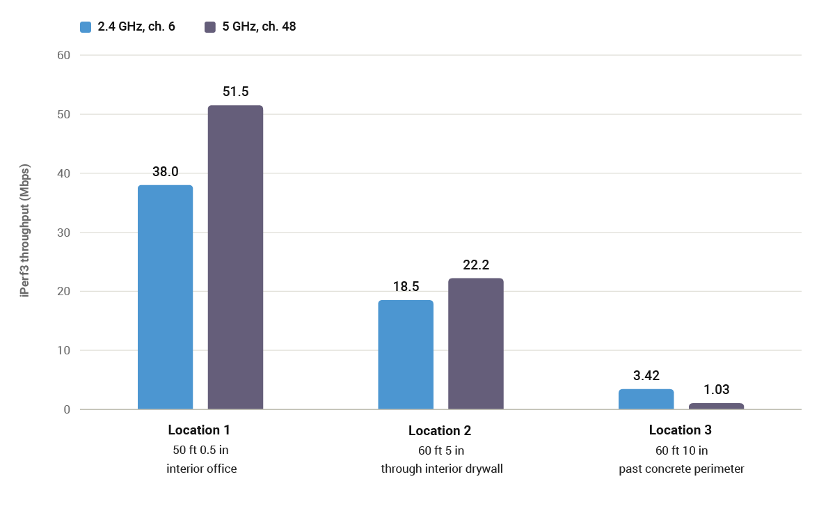
| Test location | Path from DUT | Distance | 2.4 GHz, ch. 6 | 5 GHz, ch. 48 |
|---|---|---|---|---|
| Location 1 | Interior office | 50 ft 0.5 in | 38.0 Mbps | 51.5 Mbps |
| Location 2 | Through interior drywall | 60 ft 5 in | 18.5 Mbps | 22.2 Mbps |
| Location 3 | Past concrete perimeter | 60 ft 10 in | 3.42 Mbps | 1.03 Mbps |
Two things stand out.
Distance is not the variable that matters. Locations 2 and 3 sit almost exactly the same straight-line distance from the device, within five inches of each other, but in different directions through the building. Location 2’s path runs through interior office walls, mostly drywall. Location 3’s path crosses the building’s concrete perimeter. On 2.4 GHz, Location 2 delivered more than five times the throughput of Location 3. On 5 GHz it delivered more than twenty times. Same distance, different construction, and the construction is what decided it. No channel selection recovers from concrete.
The band ranking flips with distance. At Location 1, 5 GHz delivered about 35 percent more throughput than 2.4 GHz, which is what wider clean spectrum promises. At Location 3, 2.4 GHz delivered more than three times what 5 GHz managed. The better band depends on where the client is standing.
That second point is the one to design around. A dual-band device that hard-prefers 5 GHz will look excellent in a demo and fail at the edge of a building.
Orientation Is a Channel Plan Variable Too
One more finding from that test worth carrying into your own designs.
When the controller was mounted so its logo sat upright in the correct orientation, the radio module ended up facing down and away from the client. The radiation pattern has a weak lobe in that direction, and the throughput data showed it.
The device was installed correctly. The antenna was still pointed at the floor.
This is worth checking early. Take the mounting orientation your product will actually ship in, cross-reference it against your module’s radiation pattern, and confirm the strong lobe faces the space where clients will be. It is a fifteen minute check that is nearly impossible to fix after the enclosure tooling is cut.
A Practical Channel Selection Sequence
For engineers specifying Wi-Fi in a connected product, here is the order that tends to work.
Survey the deployment environment, not the lab. Use a Wi-Fi analyzer in a representative installation to find what already occupies the spectrum. Lab conditions will mislead you in both directions.
Confirm your regulatory and DFS position before selecting channels. Know which channels your module and your approvals actually permit in each market you ship to. If DFS is not on the table, your 5 GHz options are nine channels, not twenty-five.
Choose the band based on where clients will be, not on peak numbers. If clients are consistently close and unobstructed, favor 5 GHz. If range and building penetration matter more, 2.4 GHz on channel 1, 6, or 11 will hold up better. If both cases exist, plan for both and let the client steer.
Default to 20 MHz unless you have measured a reason to go wider. Channel bonding raises peak throughput and raises interference exposure at the same time. In congested environments, narrower channels frequently deliver better real-world results.
Assign channels across your fleet. For multi-device deployments, spread controllers across non-overlapping channels rather than letting them all land on the same default. This is the single easiest co-channel fix available.
Validate with throughput testing, not signal strength. RSSI tells you a radio can hear another radio. Throughput tells you whether the link does its job. Test at the distances and through the materials your product will actually face.
The Bigger Point
Channel planning is real engineering and it is worth doing well. It is also the last twenty percent of the problem.
Peak gain, TRP, and channel selection all describe conditions the antenna sees. Real deployments add enclosures, mounting hardware, building materials, orientation, and dozens of other radios competing for the same airtime. The only way to know how a device performs in that environment is to measure it there.
That is why our RF team runs throughput and packet error rate testing on full assemblies in real buildings rather than stopping at chamber measurements. The chamber tells you the antenna works. The office tells you the product works.
If you are specifying a wireless module for a connected product and want to talk through band selection, antenna integration, or test methodology, our applications engineering team is available to help.