


Why Antenna Specs Alone Don’t Tell You How an RF System Performs
When engineers talk about RF performance, two numbers come up again and again: peak gain and average TRP.
They sound authoritative. But on their own, they only tell part of the story.
Here is why, and what actually captures how a wireless system performs in the real world.
What Peak Gain and TRP Actually Measure
Peak gain and average TRP are antenna-centric figures of merit.
In plain terms, they describe:
- The direction (or directions) where the antenna radiates most strongly.
- The total average power radiated across all directions.
- How efficient the antenna is.
That is useful. But notice what is missing: everything else in the system.
The Whole RF Chain Matters
A real RF system is more than an antenna. The signal passes through baseband processing, mixing, filtering, and amplification (LNA and PA) before it ever reaches the air.
To judge the full chain, engineers use throughput testing. It measures how the entire system performs end to end, not just the antenna.
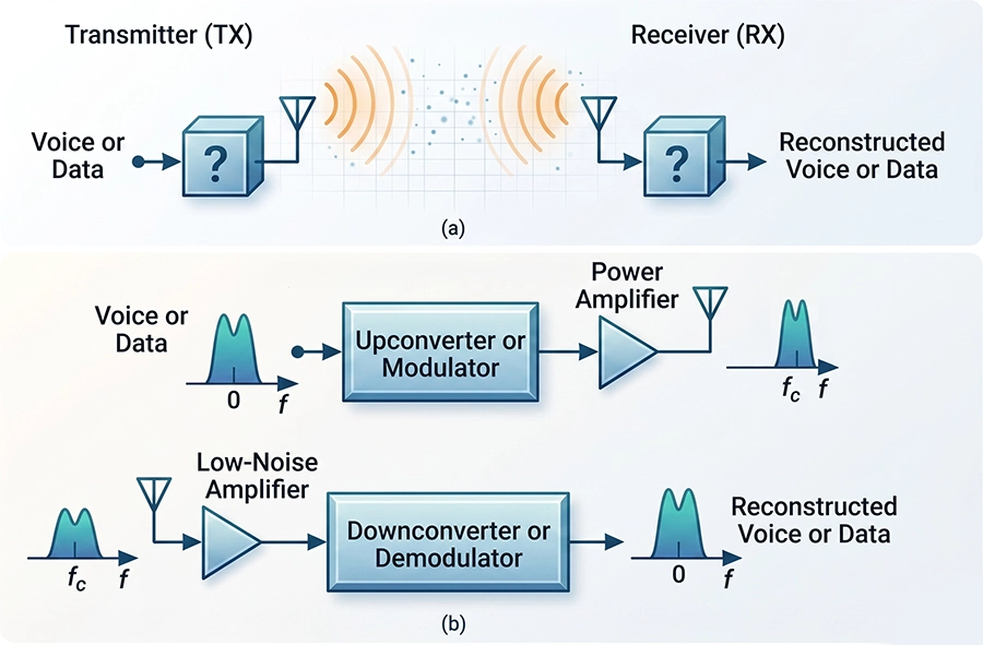
Transmitter and Receiver, Briefly
Most RF systems have at least a transmitter and a receiver separated by some distance.
The transmitter:
- Takes the data.
- Modulates it.
- Mixes it up to the carrier frequency.
- Amplifies it.
- Sends the encoded carrier signal into the propagation medium.
The receiver does the reverse:
- Amplifies the incoming signal.
- Mixes and filters it down to baseband.
- Demodulates it.
- Recovers the original data.
Where Real Systems Fall Short
Every stage above introduces non-idealities. These are the gaps between theory and reality.
Baseband processing struggles when there is low signal-to-noise ratio (SNR), multipath fading, or strong interferers that earlier stages failed to reject.
Amplifiers add their own noise, which degrades SNR. They are also non-linear, creating extra even and odd-order harmonics that may need to be filtered out.
Filters are built from components with finite quality factors (Q). That raises insertion loss, which again degrades SNR.
A few more culprits round out the list:
- Phase noise.
- I/Q phase imbalance.
- Power amplifier compression.
- DC offset.
Then There Is the Real World
All of the issues above live inside the transmitter and receiver. But there is one more factor that is just as important: the propagation environment.
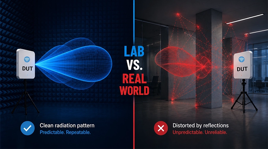
Peak gain and TRP are measured in an anechoic chamber, which simulates radiating into free space.
Real environments are nothing like free space.
The Antenna Is Never Truly Alone
In the field, the antenna is coupled to its enclosure, nearby dielectrics and metals, and the Earth’s ground.
This coupling causes two problems:
- It detunes the antenna.
- It creates lossy images of the antenna.
The result can be a significantly distorted peak gain and radiation pattern, different from what the chamber measured.
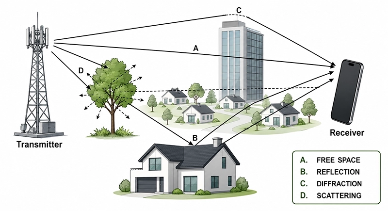
Obstacles Bend and Bounce the Signal
Once the signal leaves the antenna, it runs into buildings, cars, mountains, and valleys.
These obstructions cause specular and diffuse reflection, producing slightly delayed copies of the signal.
That leads to multipath, or Rayleigh fading, which shows up as periodic notch filtering in the frequency domain.
Add distance and polarization mismatch, and the real-world picture gets messy fast.
Peak gain and average TRP are valuable, but they assume the antenna lives in free space. They cannot capture how the full system behaves.
To know the real performance, you have to measure throughput or packet error rate across the entire RF chain, in a realistic environment.