


Wi-Fi IoT Module for Monitoring Application
CEL’s dual protocol ARM M4/M0 based module, the CMP40x0, is a low-power WiFi and BLE solution. Reffered to in this post as the CMP40x0, the CMP4010 is (2.4GHz) single band, CMP4020 is (2.4GHz and 5GHz) dual band. The smart plant monitoring application outlined in this blog post demonstrates the ability of the CMP40x0 to function as a low-power connected module. The CMP40x0 will function in a variety of networking environments.
Table of Contents
- 1. Introduction to the CMP40x0 Smart Plant Monitoring System
- 2. Features and Functionality of the CMP40x0 Plant Care Application
- 3. Sensor and Hardware Setup
- 4. Photoresistor Setup and Integration
- 5. Capacative Soil Moisture Sensor Integration
- 6. BMP388 Temperature and Pressure Sensor Integration
- 7. Growlight Relay Control Setup
- 8. "Water-me" LED Indicator Setup
- 9. Overview of Application Software Components
- 10. Network Thread
- 11. The IO Subsystem
- 12. Data Tag Thread
- 13. MQTT Interfaces
- 14. MQTT Client Historian End-to-End Data Transmission
Introduction to the CMP40x0 Smart Plant Monitoring System
I’ve used the CMP40x0 to enable sensors and developed an application to monitor the health of a potted plant.The application is currently sitting on my home network providing “water-me” notifications to a plant enthusiast (myself), but it could easily do the same on an industrial agriculture network generating data for intelligent crop care decisions.
In many control environments, the simple addition of time stamped process data on a desktop can make invaluable differences in longterm process improvements. The primary goal of this application is to use the CMP40x0 to provide the user with data on a desktop, that they can manipulate however they see fit. It is from this data that inefficiencies can be uncovered and improved upon. As this relates to inefficiencies in plant care, the smart plant monitoring system may illustrate issues with watering schedules, overwatering, over and under lighting, soil problems, and even too extreme of changes in environment temperature. This could serve plant enthusiasts and the agricultural industry alike as an application. But it’s underlying platform, and support thereof, provides CEL’s customers with a path to a CMP40x0 application that packages and sends off gathered data to a network.
The underlying platform, based on the concept of “data tags” borrowed from industrial automation will be discussed more in a future blog post, so stay tuned! For now just think of it as a way to “tag” a data point on a network.
NOTE: All code for this project is maintained in CEL’s private repository. It is available via NDA to inquiring customers.
Features and Functionality of the CMP40x0 Plant Care Application
On boot up in a new networking environment, the CMP40x0 will ask for credentials via UART, or a Bluetooth provisioning connection. Once the correct credentials are given, the application will write them into flash for fast reconnect on every reboot. This includes the application MQTT information. Credential storage enables power saving through entering low-power, non-runtime modes that turn off the onboard RAM.
The application has 5 onboard sensor/hardware pieces that it manages via an IO subsystem with appropriate drivers. These sensors are checked at regular intervals and notify the user of any environmental issues. The primary environmental issue being the level of soil moisture, which rookie and veteran plant enthusiasts alike, struggle to keep at an adequate level. The “water-me” LED will turn on if the soil moisture sensor level drops below a level deemed by the user to be inadequate. The level of “water-me” indication is currently hardcoded into the application, but future iterations of this platform could enable remote MQTT based tag configuration commands. This would include setting the level at which this alarm is triggered and the update interval.
The CMP40x0 publishes all changes of onboard data tags to the network. This can be tweaked so that certain tag state changes don’t trigger messages on the network, as packet sending costs battery life, and can overload a network if not controlled correctly. The addition of the MQTT connection enables many more user application interfaces, including emails, and push notifications. In addition, the data generated in the CMP40x0 can be historized and analyzed to make better plant care decisions in the future.
Sensor and Hardware Setup
The application interfaces utilize 3 input sensors that are read and update 4 values in the application. The application also utilizes an external LED and optional relay controlling a grow light. Hardware used is as follows:
1). Photoresistor - Generic photoresistor placed in a simple voltage divider. Available here
2). Capacative Soil Moisture Sensor - PCB trace soil moisture sensor. Capacitance reading translated to analogue value output. Available here
3). BMP388 Temp and Pressure I2C sensor - Actual sensor is made by Bosch Scientific. Adafruit breakout board availailable here
4). Growlight Solenoid - Generic solenoid used to control a store bought grow light. Available here
5). “Water-me” LED - Generic LED found in any Arduino or Raspberry Pi hobby kit. Available here
Aside from the purchased sensors, the application runs on a CMP4010 evaluation board, but can also run on the CMP4020 with one configuration change to enable dual band WiFi. The sensors are connected to the CMP4010 via a protoboard circuit. All sensors can be directly connected to the CMP4010 except for the 5V relay, which needs a voltage shifter to properly interface with the 3.3V output of the CMP4010.
Photoresistor Setup and Integration
The photoresistor was placed on the protoboard in a typical voltage divider. The divider consisted of 2kOhms ontop of a 10kOhm photoresistor. This divider was powered by 3.3V and connected to one of the 7 onboard ADC channels, PB_4. Additionally, since it is a voltage divider, the circuit requires a 3.3V connection and a GND. The signal has a range well within the bounds of the onboard 16 bit ADC. This sensor is read and placed into the PHOTORESISTOR_TAG data tag. The read function of this sensor is shown below:
int photoresistor_read(int ctl_val)
{
    uint16_t photoresistor_raw_val;
    //read 16 bit unsigned from ADC
    photoresistor_raw_val = analogin_read_u16(&adc0);
    printf("Photoresistor subsys value:%d\n\r",photoresistor_raw_val);
    //populate my_value with the sensor read value
    return photoresistor_raw_val;

}
Capacative Soil Moisture Sensor Integration
The soil moisture is read as an analogue value from the soil sensor. This value ranges from 3.3V to 0V, aside from a signal wire, the sensor requires a 3.3V and GND line from the protoboard busses. The signal wire is connected to one of the onboard ADC channels, PB_7. The sensor also needs a 3.3V connection and a GND. This value is read and placed into the SOIL_MOISTURE data tag. The read for the capacitive sensor is the same as the read for the sensor in the above section.
BMP388 Temperature and Pressure Sensor Integration
The BMP388 sensor is connected to the CMP4010 via an I2C bus with two external 4.7kOhm pull up resistors on the SDA and SCL busses. An additional few connections were made, powering of the sensor, as well as the pin connection that sets the I2C address of the sensor to GND. The sensor connects the data SDA, and clock SCL, via pins PB_5 and PB_6. This sensor is read by two different tags, both the temperature tag: TEMP_TAG and the pressure tag: PRESS_TAG. They are read at different intervals, and represented as different values on the network. The only difference is the instruction sent to the driver from the data tag structure. The read function for this sensor looks like the following:
int temp_pressure_read(uint32_t ctl_val)
{

	struct bmp3_data data;
	struct bmp3_status status = { { 0 } };
    uint32_t temp_pressure_raw_val;
	char print_buf[100];
	uint32_t combined_i2c;
	_memset(&i2cdatarddst[0], 0x00, I2C_DATA_LENGTH);
	//set data write to register address 05h
  	// Master read - Slave write
	/*
	* sensor_comp |   Macros
	* ------------|-------------------
	*     1       | BMP3_PRESS
	*     2       | BMP3_TEMP
	*     3       | BMP3_ALL
	* */

    //read the value of my_value from memory if one, read pressure, else read temp
	if((uint32_t) ctl_val & 0x01){
		//pressure read
		bmp3_get_sensor_data(BMP3_PRESS, &data, &dev);
		bmp3_get_status(&status, &dev);
		temp_pressure_raw_val = data.pressure;

	}else{
		bmp3_get_sensor_data(BMP3_TEMP, &data, &dev);
		bmp3_get_status(&status, &dev);
		//scale the temperature up for fidelity for now
		temp_pressure_raw_val = 1000*data.temperature;
	}
	printf("Temp Press subsys value:t[%d] p[%d]\n\r",(uint32_t)(data.temperature*1000),(uint32_t)data.pressure);
	return temp_pressure_raw_val;

}
In the future, read times could be sped up here by reading both of the values at the same time and just parsing the data structure out in the data_tag thread.
Growlight Relay Control Setup
An external relay is attached to the CMP40x0 via a bidirectional voltage shifter. The bidirectional voltage shifter is connected to the CMP40x0 gpio output on the 3.3V side and connected to the control pin of a relay on the 5V side. This relay is driving the connection that powers a grow light, this can be made to trigger based on a timer value, a photoresistor reading, or even time of day. The GPIO output is connected to the pin PB_1. Of course, this sensor tracks back to a data tag structure for representation on the network. This tag is named GROWLIGHT. The driver write function for this looks like the following:
int grow_light_write(uint32_t ctl_val)
{
    printf("Grow Light subsys value:%d\n\r",ctl_val);
    //write the ctl val to the gpio_write mbed api
    gpio_write(&grow_light,ctl_val);
}
Future implimentations of this growlight might utilize a BLE controller to trigger the growlight relay. In application, this relay will find itself near an outlet and likely far away from the CMP4010 running the monitoring application. The implimentation of this could be as simple as sending the growlight tag over Bluetooth to one of our BLE modules, like the CMP53x.
“Water-me” LED Indicator Setup
This LED is connected straight to a GPIO output of the CMP40x0. This line is held low until it is time to luminate the “water-me” LED. The other side of the LED is connected to a resistor going to ground. This GPIO output value tracks to PB_2. This value is driven by the data tag structure for this sensor called WATER_ME_LED. This will be driven by the soil moisture tag alarm when the value read from the sensor meets a certain user defined threshold for requiring a water.
Overview of Application Software Components
The following sections define the abstract pieces to this application. They all work together to create a balanced application. The Network thread manages the module connections, the IO subsystem manages the hardware, and the data tags drive the gathering and sending of the data collected.
Network Thread
The network code is designed to establish a network connection and store all connection data in flash. Once the credentials are written to flash, connecting to an access point requires a lot less power. It also enables the module to turn on it’s power gate, turning off the power to the RAM. With the reconnect functionality, the module comes out of this state and quickly recreates the connections stored without any user input. This includes MQTT reconnect, with MQTT credentials written to flash, the module can go from a power saving state to a fully cloud-connected state, in a short amount of time.
The IO Subsystem
The IO subsystem is simply housing common driver code in a standardized access structure. It is a standard piece to RTOS applications and is highly recommended in our SDK. All of the integrated drivers use the MBED api native to the CMP40x0 SDK, except for the temperature and pressure sensor. The temperature and pressure sensor driver had a publically available repository that was brought into the SDK. With a few platform specific tweaks, it is a fully functional port.
The project utilizes an IO subsystem to house driver code. This folder contains a target for each driver, containing that drivers five generic io_subsystem functions: xx_read(), xx_write(), xx_init(), xx_close() and xx_io_ctl(). The xx suffix is to be replaced by the sensor name. Not every sensor will have every function.
Data Tag Thread
This application layer program is a lightweight program that manages the data in the data tags. The thread sends requests to the IO subsystem thread for manipulating the sensor drivers. This occurs at intervals dictated by timing values placed into the data tag structure. The application will be initialized with a number of data tags equivalent to the data points being monitored. For this particular application, that worked out to six data tags working with five sensors.
MQTT Interfaces
The primary wireless protocol used is MQTT. This protocol is lightweight and is native in our maintained SDK. In the case of the Plant-App, the MQTT api was used to publish messages to a cloud-based MQTT broker. There is also a CMD folder that each app subscribes to for remote MQTT commands. These commands can trigger a tag forced value, a tag read, and an OTA update. On this MQTT broker, the topic structure is as follows:
<MQTT Broker>
│
└───plantbot00		#topic for plantbot00 CMP4010
│   │
│   └───CMD         #subtopic for the plant to receive messages
│   └───PRESSURE	#subtopic for the pressure reading from the BMP388 connected to the CMP4010
│   └───TEMPERATURE	#subtopic for the temperature reading from the BMP388 connected to the CMP4010
│   └───PHOTORESISTOR	#subtopic for the photoresistor readings from onboard CMP4010 ADC.
│   └───SOIL_MOISTURE	#subtopic for the soil moisture sensor reading from onboard CMP4010 ADC.
│   └───GROW_LIGHT	#subtopic for the grow light digital output control. Will send MQTT messages on state change by default.
│   └───WATER_ME_LED	#subtopic for the water me LED. This tag is dependent on the value of the soil moisture tag, but will send MQTT messages on state change by default.
│
└───plantbot01		#topic for plantbot01 CMP4010. This is a copy of the same applicaiton running on a different CMP4020 with a different plant subject.
.
.
.
The SDK has a JSON api that is lightweight and packages the information for send off quickly. Another benefit to the JSON data is how universal it is. The information can be processed in most computational environments when it is packaged in JSON.
MQTT Client Historian End-to-End Data Transmission
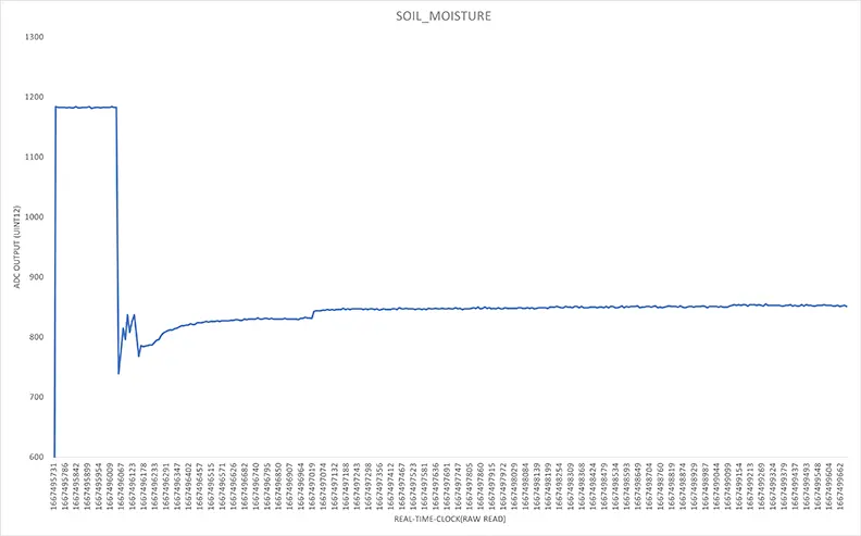
The MQTT client application is running on a desktop. It is a clean and simple Python application that subscribes to the MQTT subtopics of each tag of each plant application. The data is timestamped and labelled before it is placed into the CSV file. The main function of this MQTT client is to historize the environmental data from the plant. With the data historized, we can use trends in said data to make educated adjustments to the plant care schedule and the plant location.
This was the first watering of the plant that was captured by the plant application. A field grade application would have a much wider range that the signal would cover, taking full advantage of the CMP40x0 onboard ADC.