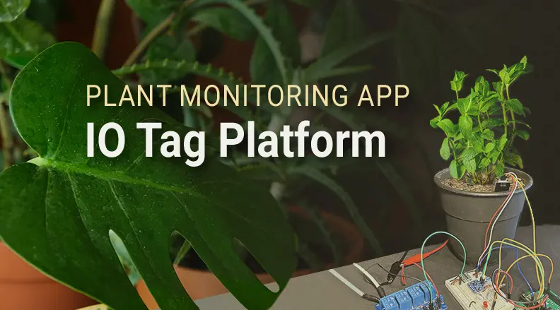


Plant Monitoring Application IO Tag Platform
A fully leveraged CMP40x0 can bring WiFi and Bluetooth to an embedded application for months (or years) on a single battery. This kind of performance is only achieved with a healthy balance between data collection and power saving. CEL has developed a platform for the CMP40x0 that attempts to offer tools for finding and maintaining this balance in embedded WiFi/BT applications. The system outlined in this document is the core of the plant monitoring application highlighted in part one of our plant monitoring app series. This application platform runs on the CMP40x0 (CEL’s low power WiFi/BT solution), dedicated to generating valuable data in a power-constrained wireless environment. While this platform is the core of the plant monitoring application, it can compliment most embedded wireless applications.
Variables in a plant’s environment are slow changing, and an environment like this gives our application ample time to enter deep-sleep. Our platform determines when it is best to save power given the application IO servicing periods and the observed RF environment. Although this application has long intervals between samples, the platform can operate with short intervals as well.
Table of Contents
- 1. Plant Monitoring Application IO Tag Platform
- 2. Application IO Tag Structure
- 3. Application State Holdover - Retention RAM Deep-Sleep
- 4. Application IO Thread and Monitor
- 5. Tag Service Loop
- 6. Tag Down-Time Calculations
- 7. Second Half of Service Loop
- 8. Network Monitor Thread
- 9. Network Functionality
- 11. Centralized MQTT Python Applicationy
- 12. Power consumption data, systems on vs. systems off
- 13. START
- 14. DSLEEP
- 15. FLASH
- 16. AUTO
- 17. Conclusion
Application IO Tag Structure
The entire application is driven by the values contained in the application IO structure. This simple structure contains a value of data accompanied by control and acquisition information. It acts as a focal point for all aspects of data collection and distribution in the system. When a tag is set to update, the application will initialize and read/write to a peripheral.
The IO structure and functionality was inspired by the “tags” at the core of many industrial automation control systems. The term “tag” loosely refers to a physical variable that is tracked over time. There is a lot of metadata associated with a physical variable in an industrial environment. That metadata is processed in addition to the IO data in a tag. Alarm states, data validity, and related connectivity measurements all fall into this metadata category. The tag containers give IOT applications on the CMP40x0 a place to put all of this information regardless if it is entering or exiting the application.
The app IO structure and associated API code is meant to compliment IOT application development. Rather than worrying about application wireless interfaces and power saving, a developer can work on proprietary code and driver development to prove out functionality and quickly develop an app with multiple flexible interfaces. The developer will only have to worry about generating the data. The process of aquisition and send off can be managed by this platform.
Application State Holdover - Retention RAM Deep-Sleep
When the CMP40x0 enters deep-sleep, it’s lowest power state, it turns off the MCU RAM. Since this application enters and exits deep-sleep so often, it needs a way to maintain information through a deep-sleep; enter the retention RAM.
Retention RAM is the star of the show when it comes to power saving on the CMP40x0. It enables the platform to quickly query the app status register and know what the module needs to do next, even when waking. The retention RAM is 178 bytes that maintain state through deep-sleep and can be read easily throughout an application. In this implimentation, the retention RAM is used to cycle through application state changes while simultaneously dropping into power saving states. Rather than booting up from a blank slate, different tasks can be started and tweaked based on what is read from the retention RAM.
Aside from storing the app state, retention RAM is also used to manage the FIFO flash system. This part of the application stores tag data in flash if the RF environment is too harsh. The registers used for this application are shown below. Each bit signifies a task or tasks to start. There are other bits in the control registers that are used to manage tag storage and network throughput, below shows the bit masks for the app status register.
#define G_RESET_APP_START 0x01  //global flag for the app waking up from reset
#define DSLEEP_DTIME_SET 0x02   //bit to set when down time is written to rram
#define EVAL_INTF_START 0x04
#define MQTT_APP_START 0x08
#define BT_APP_START 0x10
#define HTTP_SERVER_START 0x20  //high consumption task, useful for debug
#define TAG_UPDATE_START 0x40
#define TAG_SEND_OVERRIDE 0x80  //overrides other applications and sends out tags
Application IO Thread and Monitor
The core of the data acquisition occurs in the app_io thread. This thread only runs when it is determined it is appropriate. Prior to booting this thread, the module will have connected to an access point and all wireless interfaces. In this case, the wireless interface was a simple connection to a cloud MQTT server. This thread manages and houses the data gathering process. The application IO structure includes registers for the current tag statuses and required service flags. These registers are checked in a loop by the app_io thread. If a control register is checked and it is determined a flag has been set, application IO service will be initiated.
Tag Service Loop
The service loop makes calls to a few api functions, the first of which is the tag_update_check() function, this function will set the IO status registers if the refresh period is less than the time since last service. The next function, tag_alarm_check() checks the alarm status register for a triggered alarm, calling the alarm callback function if it is deemed the tag is in an alarm state. The last function, tag_io_check() checks the tag control registers and will send off requests or commands to the IO subsystem as needed. The IO subsystem will process this command and respond appropriately. All this can be done while an application is running on the module. A developer could impliment simple additions, like PID loops, or more complex additions, like a display and GUI application.
In all cases, an event or change to the application IO structure will trigger additional services or driver commands. This includes sending off tag updates to the network monitor. The service loop ends with an evaluation for down time. This down time evaluation is discussed in more detail in the next section. See below for the first half of the application IO service loop:
		if(xSemaphoreTake(tag_access_sema,1000)!= pdTRUE)
		{
			DBG_PRINTF(MODULE_APP,LEVEL_ERROR,"tag_access_sema take failed\n\r");
		}

#ifdef CONFIG_TAG_DSLEEP
        //begin the evaluation of the tag down-time
		if(!app_mode_sema_check(DSLEEP_SEMA)){
			start_tag_dsleep_eval();
			time_since_start_time = 0;
			DBG_PRINTF(MODULE_APP,LEVEL_INFO,"app_io_thread dsleep_sema is taken\n\r");
		} else {
			start_tag_dsleep_eval();
		}
#endif
		//loop through all tags, updating all of them
		for(i=0;i<NUM_OF_APP_IOS;i++){
			//update tag IO status and Alarm status for this pass
			error_check = tag_update_check(&g_app_io_array[i],time_since_start_time);
			if(error_check!=0){
				DBG_PRINTF(MODULE_APP,LEVEL_ERROR,"app_io thread error number%d\n\r",error_check);
			}
			//check for alarms that need to be addressed with a callback function
			error_check = tag_alarm_check(&g_app_io_array[i]);
			if(error_check!=0){
				DBG_PRINTF(MODULE_APP,LEVEL_ERROR,"app_io thread error number%d\n\r",error_check);
			}
			//Check IO_STS register for any output refreshes. If any bits in this register are a one, the
			error_check = tag_io_check(&g_app_io_array[i]);
			if(error_check!=0){
				DBG_PRINTF(MODULE_APP,LEVEL_ERROR,"app_io thread error number%d\n\r",error_check);
			}
#ifdef CONFIG_TAG_DSLEEP
			//check for a tag refresh trigger. If one exists, evaluate time to trigger
			if(!app_mode_sema_check(DSLEEP_SEMA)){
				error_check = add_tag_to_dsleep_eval(&g_app_io_array[i]);
				DBG_PRINTF(MODULE_APP,LEVEL_INFO,"app_io_thread dsleep_sema is taken\n\r");
			} else {
				error_check = add_tag_to_dsleep_eval(&g_app_io_array[i]);
				if(error_check!=0){
					DBG_PRINTF(MODULE_APP,LEVEL_ERROR,"app_io thread error number%d\n\r",error_check);
				}
			}
#endif
		}
		xSemaphoreGive(tag_access_sema);
Because the tags sit in an area of memory that is a shared amongst tasks, there is a semaphore named tag_access_sema which a task must have taken before it can access the tags. This type of computational structure is seen throughout many RTOS based applications. It coordinates access to memory, among other things, between separate tasks and modules in an RTOS application.
Tag Down-Time Calculations
An important part of the application power saving abilities is the tag down-time evaluation. The function call add_tag_to_dsleep_eval(&g_app_io_array[i]); in the above code adds a tag to this calculation. The function call check_dsleep_eval();, does a check for how long deep-sleep is possible given the nearest required service time. The check function populates the retention RAM registers accordingly in preparation for deep sleep entry. Upon waking up, the process can start all over again. This calculation takes into consideration the timeline for all of the data that is to be gathered given the modules current configuration. The platform utilizes the onboard real-time clock(RTC) and associated wake-up method to wake-up and service the tags on schedule. After the calculation determines that the last tag in the acquisition loop has been refreshed, the system is reset, resetting the retention RAM and all associated variables.
Second Half of Service Loop
This half receives those messages and sets them as the new value for the application IO with a call to the function tag_set_val(). This call will trigger messages to the network monitor with the new tag value for logging on module or send off to a server. This messaging reception is shown below:
            if(os_msg_recv(io_subsys_handle, &io_msg, 0) == true){
                if(xSemaphoreTake(tag_access_sema,1000)!= pdTRUE)
                {
                    DBG_PRINTF(MODULE_APP,LEVEL_ERROR,"tag_access_sema take failed\n\r");
                }
                if(g_app_io_array[io_msg.tagtype].IO_CTL&INPUT_MASK){

                    tag_set_val(&g_app_io_array[io_msg.tagtype],(int) io_msg.data.buf);
                }
                xSemaphoreGive(tag_access_sema);
            }
Having all of the functionality start and end with the IO tags gives the developer a single place to interface with and manage during runtime. This interface is configurable via application defined commands that currently are accepted through MQTT but could be expanded to UART, BLE or similar interfaces.
Network Monitor Thread
The data acquisition monitor task, sends the data gathered to the network monitor. The network monitor task receives the data and either forwards it to the relevant wireless interfaces, or places it into flash storage for relaying over the network at a later time. For the plant application, the module is either in a START mode, or one of three power-saving and storage modes. In START mode, the module will send all of the messages that are received by the network monitor thread out over the application wireless interfaces. In the power-saving and storage modes, DSLEEP, FLASH, and AUTO semaphores are taken and given based on what the system needs. As these semaphores are taken and given, the module will place all of the recorded data, with a time stamp, into flash, or it will wait for a manual command/emergency send message from the MQTT broker, or wait for a low traffic time if in AUTO mode.
The primary consideration in a low-power wireless application is the type of network and RF environment the module will be in. Ideally, the module will be on an IOT network with only other plant monitoring applications on it. However, even with their own network, external networking variables can effect power consumption and throughput when it comes to RF. Likely, the application will be in an environment that has a lot of noise in the WIFI band. Any 802.11 packet sent within a certain radius, regardless if it is meant for the same network, will hit the antenna of both the access point and the end device and demodulated by the hardware. This will consume power when the module is idling, and also create problems for the module sending out data (assuming the noise floor is high enough). The developer has to make sure that the packet sent has minimal interference and is received by the AP. The faster the packet is successfully sent, the more battery is saved. The network is evaluated at predefined intervals in search for these “low-traffic” times.
Network Functionality
The application IO structure contains fields for metadata collection, information on when and why the data was collected, networking data, and the exact time-from-epoch the application IO thread received the information from the sensor. The networking environment data is crucial as the information passed off to the server is vital for determining how best to save power.
The following if() statement is an important part of the tag_traffic_manager() function which is started by the network_monitor thread to manage network traffic. As you can see, the monitor loop receives the messages from net_handle and sends them either to the flash for send off later on, or straight to the wireless applications. The below logic shows off how all of the app mode semaphores dictate the end location of the tag generated
//send off to a wireless task or store in flash for future sendoff
if(app_mode_sema_check(FLASH_STORE_SEMA)){ //FLASH mode
//check interface viability and application mode before sending tag
if((wlan_viability > INTF_VIABIL_THRESHOLD)&&(app_mode_sema_check(AUTO_EVAL_SEMA))){ //AUTO mode and interface is viable
char_ptr = generate_tag_json_data((P_APP_IO)net_msg.data.buf);
if(rram_sts_reg & MQTT_APP_START){
net_send_msg(NET_MSG_TO_MQTT,net_msg.subtype,char_ptr);
} else {
DBG_PRINTF(MODULE_APP,LEVEL_ERROR, "MQTT app isn't in start state in retention RAM\n\r");
}
}
else{ //flash
//send data to the end of the FIFO stack
memcpy((uint8_t*)©,(uint8_t*)net_msg.data.buf,sizeof(APP_IO));
write_tag_to_flash(copy);
}
} else {
char_ptr = generate_tag_json_data((P_APP_IO)net_msg.data.buf);
net_send_msg(NET_MSG_TO_MQTT,net_msg.subtype,char_ptr);
}
Centralized MQTT Python Application
In our setup, the central entity is a Python application running on a Raspberry Pi. The Python application on the Raspberry Pi is subscribed to all of the sensor topics for each module. Once this message is received by the Python app, these JSON messages are parsed into a row in a CSV file, see filewriter.writerow(). The CSV file can be used to visualize and historize the data gathered. The storage and power-saving mode that has been discussed will not send off these packages to the wireless interface, it will store them in the flash. The code that subscribes the python app to these sensor topics is as follows:
client.connect(broker_url, broker_port) #connect to the MQTT broker

#subscribe to relevant topics
client.subscribe("plantbot3000/SOIL_MOISTURE", qos=2)
client.subscribe("plantbot3000/PHOTORESISTOR", qos=2)
client.subscribe("plantbot3000/GROW_LIGHT",qos=2)
client.subscribe("plantbot3000/PRESSURE",qos=2)
client.subscribe("plantbot3000/TEMPERATURE",qos=2)
client.subscribe("plantbot3000/WATER_LED", qos=2)
The JSON received is parsed in the callback registered for a message reception. That function is called on_message() and is defined as follws:
def on_message(client, userdata, message):


    print(my_device)
    #parse json

    try:
        tag_string = message.payload.decode()
        tag_json = json.loads(tag_string)
    except UnicodeDecodeError:
        print("Error: there was a error, skipping message")
        return
    except json.decoder.JSONDecodeError:
        print("Error: there was a error, skipping message")
        return
    print(tag_json["tag"])
    print(tag_json)

    with open('data.csv', 'a') as csvfile:
        filewriter = csv.writer(csvfile, delimiter=',',
                                quotechar='|', quoting=csv.QUOTE_MINIMAL)
        filewriter.writerow((time.time(),tag_json["tag"], tag_json["data"]["raw_val"]))
This system for app IO can be catered to the needs of many applications. The network evaluation calculations can be configured to have higher thresholds for noisier environments, or adjusted for quieter. These configurations can be made dynamically so that the system can adjust to different noise levels throughout the day during runtime. This interface and the application access it provides allows endless combination of thresholds and can even allow traffic patterns to be scheduled. As the system increases in complexity, so does network coordination. As a system like this scales up, the data processing will get increasingly complicated, luckily this system can pair up nicely with the addition of artificial intelligence on the central entiny. Likely, something like that could exponentially increase an application’s and system’s battery life.
Power consumption data, systems on vs. systems off
There are several different states the application can be in, all of which will draw different levels of power.
START
The “START” mode discussed here can be thought of as a global application start. The application network interfaces and associated application threads will boot, as well as the application IO thread and subsystems.
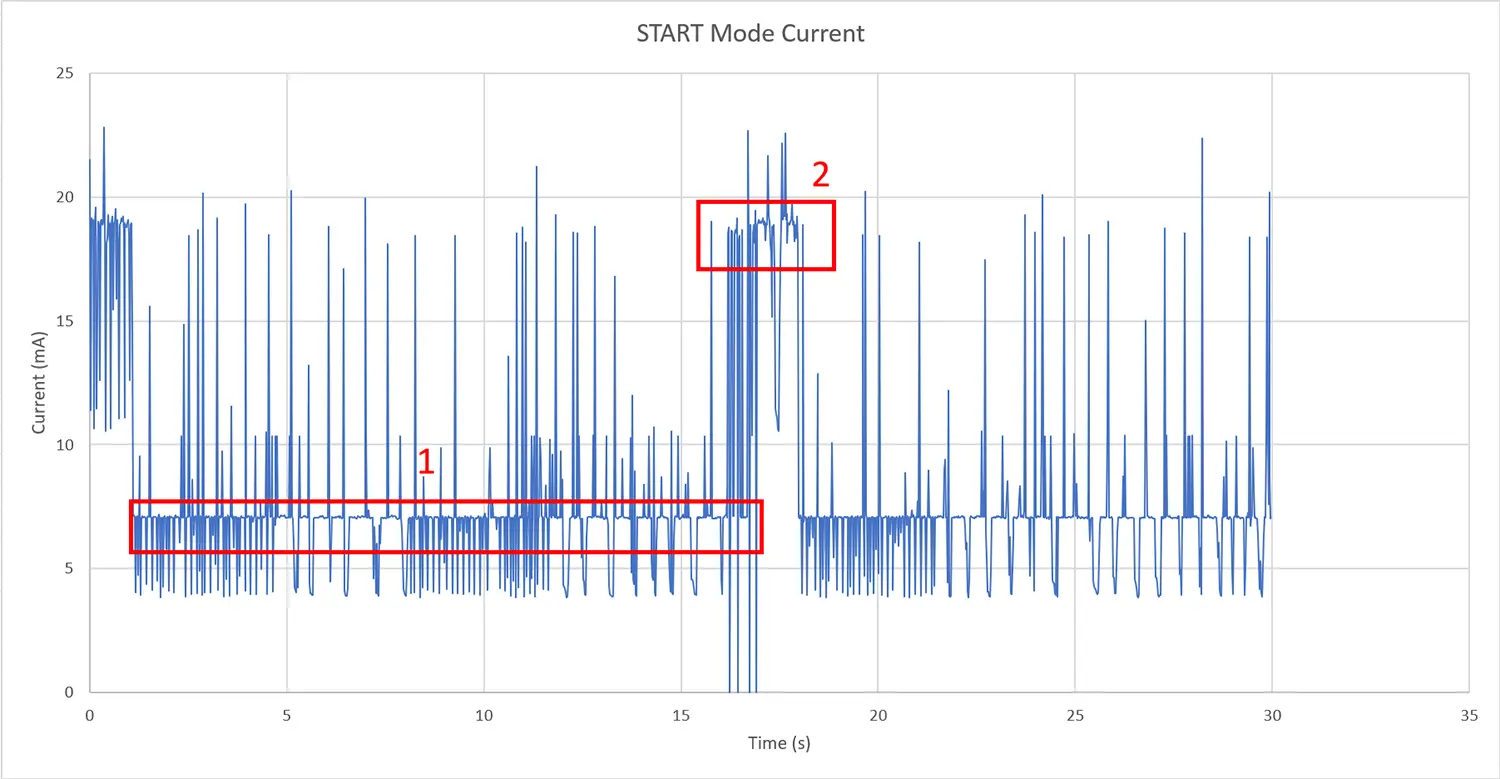
In the above plot, the first rectangle is illustrating the modules idle state. This is essentially a while loop going through and resting a task for a length of time. The second rectangle is the modules io subsystems and network interfaces booting up and sending off data. This is significantly higher than the module idle current.
DSLEEP
When in DSLEEP mode, the application will fall into deep sleep when a down time is detected between IO services. The app will briefly wake to measure the network interface noise and fall back asleep. There is a function defined in the app that manages the application sleep intervals based on it’s retention RAM state and the app mode.
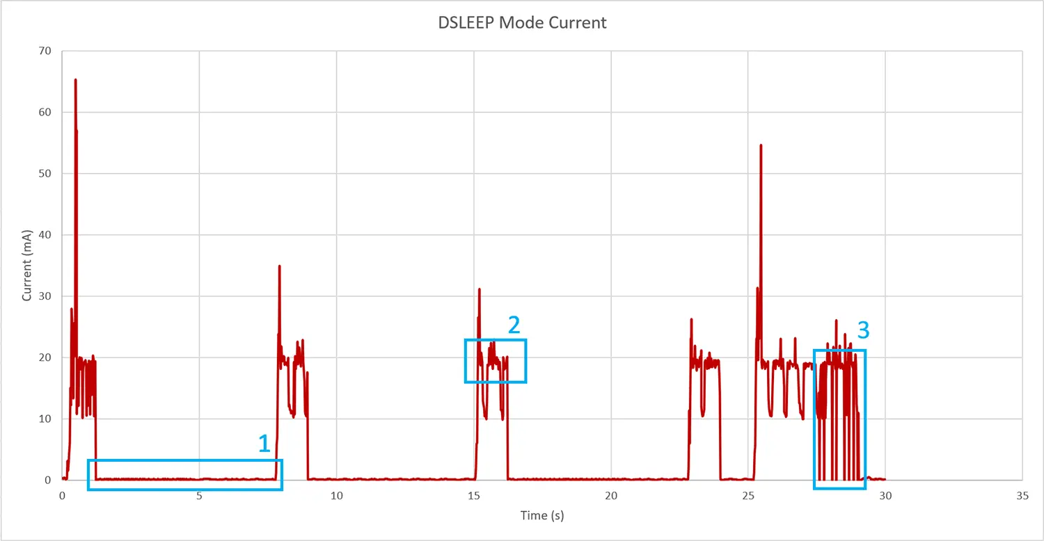
The first rectangle is the deep-sleep current of the module. While it may be hard to tell on this graph, this number is <100 micro Amps. The second rectangle is the power consumption when the application is in an interface evaluation state. At this time, the WiFi is in a passive state, but evaluating the interface. The third rectangle is at the end of the tag service period, the application sends off the packets to the MQTT server. Obviously this is an effort for the module to process and results in a longer wake time and slightly higher than average current.
FLASH
When in FLASH mode, the module will write the IO tags generated to the flash FIFO structure. Whether or not this is dependent on the interface evaluations, is dictated by the AUTO mode semaphore. If the AUTO mode semaphore is taken, the flash semaphore acts as a switch for receiving live updates or storing them for power saving. The number of packets the module is receiving is a part of the IO tag structure metadata, this can be used by a central entity to make educated decisions on when to request tags and when not. If the AUTO mode semaphore is given when the FLASH semaphore is given, the module will make interface evaluations and decide whether to send off or not based on the evaluation.
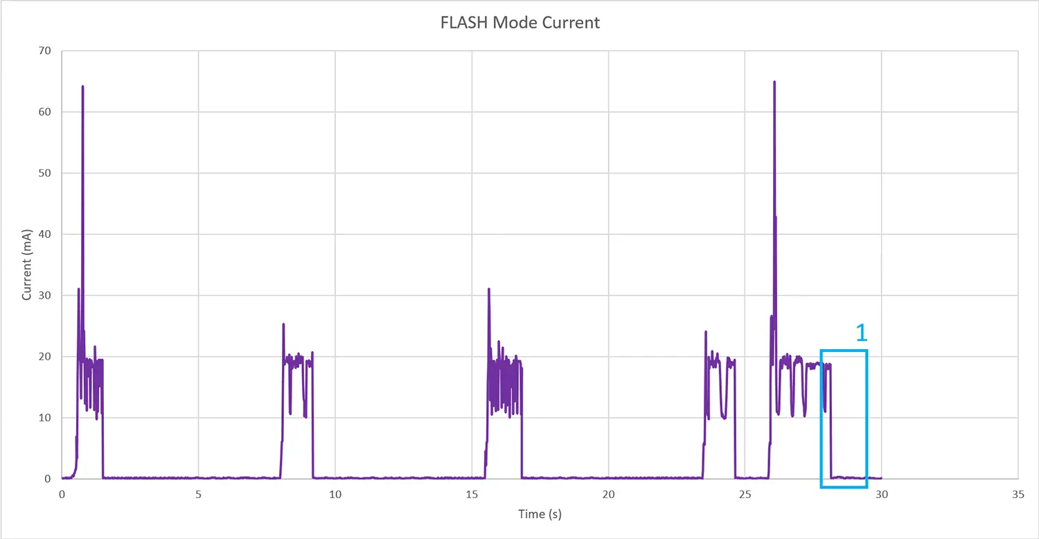
The rectangle in this plot is an area of interest because in the DSLEEP mode, this the module remains awake for this much of an extended period. The tags were written to flash rather than sent off which tends to be faster and less power consuming than a wireless send off. There is an override send off where the tags in the flash are read out to the wireless interface, but it was not captured in this graph. This override does take additional power, the key is to send it at the right time.
AUTO
While there was data captured for the application AUTO mode, it was so similar to the FLASH mode data that it was left out. The effects of this network evaluation technique would likely be seen over time and especially in noisey commercial environments. The test location was not a very busy RF environment. As the module is awake and packets hit the antenna, the current used will increase over time, reducing this exposure time is the primary focus of AUTO mode.
Conclusion
An application platform that reduces its’ power consumption significantly; allows an IoT team to push the boundaries of what is considered a wireless device. A WiFi stack that runs on a battery can bring a data focused system to incredibly novel environments, and as a result novel datasets to computational environments. This platform aims to give developers a proper starting point for developing a power constrained CMP40x0 application.
Stay tuned for our next plant-app blog post where we push this app even further. We will shift gears back into the application running on the platform and investigate further alarming and CMP40x0/CMP53x Bluetooth applications. We’ll be adding a photoresistor alarm that will trigger a grow-light wireless switch running on our very own CMP53x! The CMP53x is a Bluetooth and Zigbee/Thread/15.4 dual protocol module. The grow-light is no longer hardwired to the app, it is on line power so battery power is not an issue. That being said, the CMP53x comes with some remarkable powersaving features as well. The CMP53x will be configured as a BLE peripheral. The BLE central stack on the CMP40x0 will create a connection with the CMP53x and send on and off commands based on the photoresistor alarm states.
We will repurpose the grow light app IO tag initialized on the CMP40x0 and use it to control a BLE peripheral status. This tag change will be triggerd by the alarm of the photoresistor. The alarm will be based on how high or low the photoresistor value is. When the alarm triggers it will call the tag alarm callback which will be defined by the tag initialization process. In this case the tag alarms will trigger MQTT messages, as well as an LED to turn on for the “Water-me” LED, and now a BLE peripheral to turn on for the grow-light to turn ons.
Related Products
- CMP4010 HOSTED/HOSTLESS Wi-Fi 4 + Bluetooth 5.2 Module
- CMP4020 Dual-Band Wi-Fi 4 + Bluetooth 5.2 Module
- CMP53x Bluetooth 5 + 802.15.4 Multi-Protocol Module