


Using the Arduino IDE and HAL with the CMP40x0
CEL’s CMP40x0 can be programmed as if it was an Arduino, using any code that can run on other Arduino boards. The programming process used for the CMP40x0 is identical to that of any other Arduino board with the Arduino IDE. Programming the board this way opens the module hardware up to millions of community projects and code bases. This is perfect for a smaller budget project hoping to use premade drivers on widely available sensors, maybe to prove out an idea quickly, or simply to make it to market in a timely fashion. Of course, the same can be done by a large team hoping to use high quality sensors, still likely saving the team time on development.
Getting Started
1 Download the Arduino IDE. Install on your preferred platform, the IDE contains everything needed for building, compiling, and flashing the module. Install on your preffered platform, the IDE contains everything needed for building, compiling, and flashing the module.
2 To add the correct board manager and libraries, visit this Github repository and follow the instructions starting at step 2. This repository was made and maintained by the AmebaIOT community, their forum has a lot of useful information on the module IC as well as Realtek IOT in general.
3 Last, select the 8721DM based board from the selection, the
AW-CU488 Thing Plus. The same Arduino IDE toolset works for both modules because of the shared IC.
With the proper libraries selected and plugged in, we can begin programming and testing the board!
The Realtek defined hardware and driver calls are a part of the Arduino HAL. The HAL stands for Hardware Abstraction Layer and does just that, abstracts the software from the hardware. The kaveat to abstracting the code like this is, some digging must be done in the Arduino IDE before any Realtek code references are found. But, the underlying hardware calls and drivers are present, and behave the same on applications from the CEL NDA SDK, as they do on the Arduino IDE SDK. The Arduino HAL will handle calls to the driver and stack when a function like WiFi.begin(ssid, pass) is called. This is all thanks to the efforts of the community on the Arduino HAL library for the RTL8721D.
The examples available in the Arduino IDE library do a great job of overviewing all of the onboard bells and whistles. The examples focus on different aspects of the modules MCU, the RTL8721D, as it relates to the Arduino HAL. There are examples that put the module into low power, utilize the BLE stack, use the RTC, ADCs, flash, and even USB. On top of the hardware, there are examples exploring different wireless/IP protocols, MQTT, UDP, Bluetooth provisioning, chat servers. The list of examples available to try is endless, so this post will explore two different wireless examples that work out of the box with the CMP40x0. The first example studied is called SimpleWebServerWiFi and is a WiFi example for Arduino. The second uitilizes a DHT-11 temperature and humidity sensor to act as a BLE peripheral, called DHT_over_BLEUART. The examples show the ease of using the WiFi stack, as well as the BLE stack in the Arduino HAL.
SimpleWebServerWiFi
This example is found in the following menu folder: File > Examples > WiFi > SimpleWebServerWifi. Find it, click on it, and a new Arduino IDE window should pop up on your desktop. The example code for this “sketch” will be showing in the window. I have included the portion of the code that connects to an access point, and the necessary variables, for reference.
#include <WiFi.h>

char ssid[] = "yourNetwork";        //  your network SSID (name)
char pass[] = "Password";           // your network password
int keyIndex = 0;                   // your network key Index number (needed only for WEP)

.
.
.

    // attempt to connect to Wifi network:
    while (status != WL_CONNECTED) {
        Serial.print("Attempting to connect to Network named: ");
        Serial.println(ssid);                   // print the network name (SSID);

        // Connect to WPA/WPA2 network. Change this line if using open or WEP network:
        status = WiFi.begin(ssid, pass);
        // wait 10 seconds for connection:
        delay(10000);
    }
    server.begin();                           // start the web server on port 80
    printWifiStatus();                        // you're connected now, so print out the status
As you can see, the code in this sketch is far removed from the actual driver/WiFi stack calls. Everything is abstracted to a certain degree. This abstraction enables larger sharing and reusablity of embedded Arduino code. Rather than having the code specific to our WLAN driver in the main of the application, there are calls to functions defined by the Arduino community in the HAL. These calls are standardized so that this example will run on many different WiFi modules, as long as they have an Arduino HAL library. The standardized calls invoke calls to our implimentation of the WiFi stack, in the software subsystems.
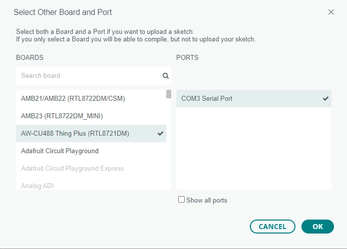
If you haven’t selected the proper board and COM port now would be a good time, click on the drop down menu next to upload button. Select the board shown below and your com port:
I have added the necessary access point credentials and compiled the sketch, let’s upload it to the modules and see what we get! To compile and upload in the Arduino IDE, press the ![]() button. After this button is pressed, you will be asked to put the module into download mode. This is done by unplugging the module, holding down the UART DL button and plugging it in, then pressing reset. If done successfully, you will see the readout:
button. After this button is pressed, you will be asked to put the module into download mode. This is done by unplugging the module, holding down the UART DL button and plugging it in, then pressing reset. If done successfully, you will see the readout:
Upload Image done.
All images are sent successfully!
Open your preffered serial terminal and open it to the COM port that the CMP40x0 is plugged into with the baudrate of 115200. Press reset and the module will attempt to connect to the local network.
After the module successfully connects to the WIFI, you will see a read out that looks like the following. This is a screenshot of a TeraTerm Window connected to the modules COM port.
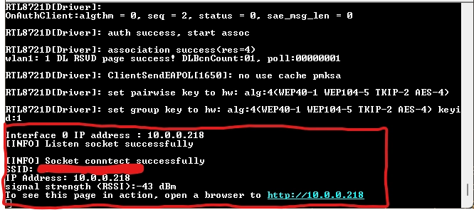
The module will read out a web address that is really just the modules IP address. Before visiting the site, get the hardware ready by connecting an LED. The LED should be connected to pin PB_29 with a resistor to ground. If your module is still connected to the internet and plugged in, you can visit the IP address of the module with any browser.
When visited, you will see the following simple HTML webpage below:
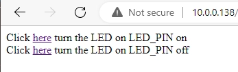
Now, you can click the here buttons to cause the LED to flash on the microcontroller over the local network!
Video

The link for the video of the demo here.
While this isn’t necessarily an ideal IOT application of the CMP40x0, it is illustrating how quick it is to hit the ground running with our module in the IOT space. The CMP40x0 has low-power modes that can be used to save power. In most cases turning on a web server is a quick way to run through your battery. Good news is there are just as many, if not more wireless examples that illustrate the CMP40x0 in a WiFi client configuration, or similar.
DHT sensor BLEUART application
Enabling and programming the module with this application are similar to the previous example, this one can be found in the following folder: File > Examples > AmebaBLE > DHT_over_BLEUART. Once it is running, you will need a BLE Central stack that you have full, live control over. CEL engineers like to use the applciation LightBlue for debugging applications like this. There are several other debug applciations we use, but this is the best for applications like this using BLEUART.
The DHT-11 sensor comes in most, if not all of the Arduino sensor kits. It is a cheap and mass produced single wire humidity and temperature sensor. This example reads the DHT-11 sensor and sends the information to a connected BLE central stack. The BLE application functions as follows, once a connection has been made to the CMP40x0, the central stack can enable notifications from the DHT-11 sensor. With notifications enabled, you will receive a BLE notification on the BLE central stack every 5 seconds with a read from the sensor in the following format Humidity:X% Temperature:Y°C. This is a live update of the values, so any external changes, such as a human breath, are very evident in the BLE notifications.
The DHT-11 sensor communicates to an MCU via a fairly unique single wire interface. The example running on the CMP40x0 will require the single wire connection to the pin PA_19, as well as ground and VCC. If we were building this application from scratch, rather than having to write or port a driver for this sensor, it was already written by a different member of the community. Since it is the Arduino HAL, we know this code was written abstracted enough to run on our hardware. This kind of thing can save small teams a lot of time, enabling fast prototyping with hardware that can be phased out, or continued support for a project that goes to production quickly with community code and widely available hardware. Below is the extent of the code that is required in the application for the sensor that was used.
    dht.begin();
.
.
.
    float h = dht.readHumidity();
    float t = dht.readTemperature();
The sensor’s driver is read and the info is placed into the BLE peripheral stack conditionally. The conditions that must be met are a connection made, and notifications enabled by the BLE central that is connected. The code required for the main loop of the application is shown below:
void loop() {
    float h = dht.readHumidity();
    float t = dht.readTemperature();

    if (isnan(h) || isnan(t)) {
        Serial.println("Failed to read from DHT sensor!");
        return;
    }

    String msg = ("Humidity: " + String((int) h) + "%\t" + "Temperature: " + String((int) t) + "°C\n");

    Tx.writeString(msg);
    if (BLE.connected(0) && notify) {
        Tx.notify(0);
    }
    delay(5000);
}
After compiling and loading this example onto the module you should see it in any Bluetooth scan as AMEBA_BLE_DEV. Once a connection is established with AMEBA_BLE_DEV, the read, write and notify service will be the one that sends out read sensor data. Select this service from the BLE central stack. Enable notifications on this connection and the data will begin to roll in!
Video

Click here for the link to this video.
If you click the link you will see that, when I breathe on the sensor that is attached to the module, the humidity sky rockets, and the temperature increases slightly. I played with the code in the application a little bit to make it so the sensor would read and notify every second instead of every 5.
Conclusion
This blog post attempted to illlustrate the ease that comes with using the CEL CMP40x0 with the Arduino IDE and consequently, the mass of community software and support available throughout the internet. The beauty of this is that the hardware and antenna design considerations of CEL contribute to the RF performance regardless of the software running on the module.
Our primary support efforts on the CMP40x0 are for the SDK we require an NDA to access. This SDK, includes security features, many more examples, a reference IOT platform, and support from our team! Reach out for information on the hardware and a consultation on what the best path forward for you’re team is.
Buy Now
Start Programming the CMP4010 with Arduino Today!
Related Products
- CMP4010 HOSTED/HOSTLESS Wi-Fi 4 + Bluetooth 5.2 Module
- CMP4020 Dual-Band Wi-Fi 4 + Bluetooth 5.2 Module