


Introducing SRR-Based SMT Antennas: High-Performance Solutions for Wireless Applications
In wireless system development, antenna, for obvious reasons, is often a critical design consideration. Traditionally, external antennas, which are usually connected to the circuit board through coaxial connectors and cables, are the design choice because of better performance and flexibility in placement. As market evolves, however, the aesthetics of a wireless product has become an important, and sometimes decisive, factor for the market success of the product. In addition, other practical considerations, such as space constraints, easy installation and low product cost, also favor an internal antenna configuration.
As a result, surface-mount-technology (SMT) antennas, are increasingly popular among wireless system designers. To meet this market trend, a new class of SMT antennas, the RAC series, was launched recently by CEL. The RAC series antennas feature compact size, high radiation efficiency as well as versatility in PCB mounting configuration. They are designed for a number of popular wireless applications including Iot (sub GHz and 2.4GHz), WiFi (including 6e) and 5G Sub-6. This note covers some technical details of this antenna product line.
Split-Ring Resonator (SRR)
Any antenna, regardless of its structure, is specified for a certain frequency range. This can be understood from the impedance-matching standpoint: the antenna acts like a resonant circuit in the sense it radiates radio frequency (RF) power efficiently only when its reactance, which is always a function of frequency, diminishes. For dipole antennas this happens when the dipole length is roughly half the RF wavelength.1
The resonance element in the RAC series antennas is a split-ring resonator (SRR) whose basic structure is sketched in Figure 1. As shown in the figure, the SRR functions as a series LC resonant circuit where the capacitance is from the parallel-plate capacitor with an air gap while the inductance from the ring. Since the resonance frequency is proportional to 1 / √LC and the capacitance is inversely proportional to the air gap (d in the figure), we can reduce the size of the ring (decreasing L) while still maintaining the same resonance frequency by narrowing the air gap (increasing C). This is the essence of how a significant size reduction, in comparison with conventional PCB or metal-plate antennas, is achieved with the SRR based antenna.
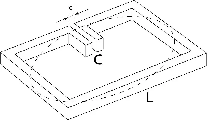
Figure 1
Basic structure of split-ring resonator. The dashed line indicates RF current.
Another significant feature of an SRR based antenna is that its resonance frequency is almost solely determined by the SRR elements. As a result, the frequency characteristics of this type of antennas is expected to be less sensitive to surrounding medium and metal objects. This is confirmed by an electromagnetic simulation of an RAC series antenna mounted on a PCB: the simulation result shows a tight confinement of the RF current around the antenna without any significant leakage to the PCB ground.
The resonance circuit is only a necessary condition for an antenna operation. To utilize an SRR in commercial antenna applications, two breakthroughs must be made:
1.) A device structure that allows efficient radiation at the resonance frequency;
2.) Precision machining capability in high volume production. The RAC series antenna is the result of years of R&D efforts in these two areas.
The SRR structure has been extensively studied and utilized in practice as a building block for the so called metamaterials which possess certain properties that do not exist in nature.2
Although the RAC series antennas, strictly speaking, are not metamaterial antenna, they may belong to a category termed as “metamaterial inspired” in the literature.3
Characteristics of RAC Series Antennas
As an example, a photo of one of the RAC series antennas, the RCA00245, which is a dual band WiFi antenna, is shown in Figure 2, along with the illustration drawing. In the following, several key characteristics are briefly discussed.
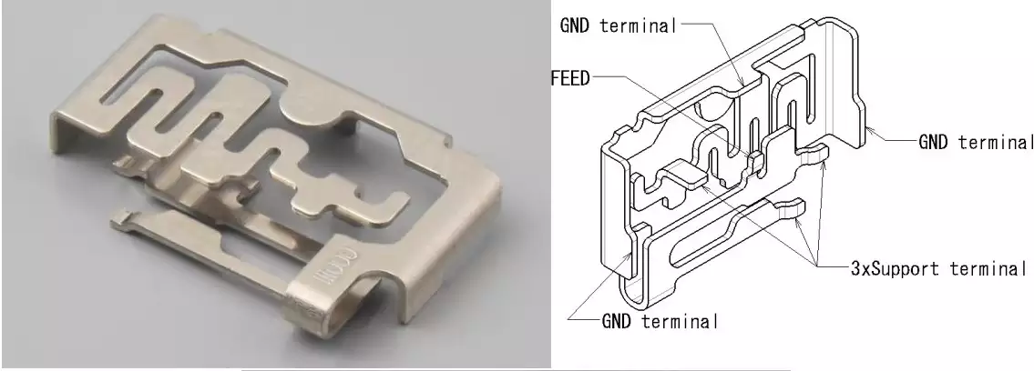
Figure 2
RAC00245 dual band WiFi antenna
Compact Size
Unlike PCB based antennas that generally require an additional keep-out area (no metal) on PCB to maintain the specified RF performance, the keep-out area for an SRR based antenna is essentially the same as the device, as shown in Figure 3. This feature, in addition to the already compact antenna size, produces a reduction as high as 70% in effective PCB area when compared with typical PCB antennas.
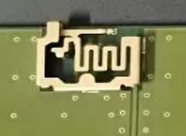
Figure 3
Keep-out area of the RAC00245
High Radiation Efficiency
While materials of high dielectric constants are one of key factors in achieving size reduction for chip and PCB antennas, these dielectric materials become lossy at RF frequencies. As a result, the radiation efficiencies of these types of antennas are generally low or moderate. In contrast, the mechanism for the compactness of the RAC series antenna is the SRR structure whose EM fields are mainly confined in the air, which essentially eliminates the dielectric loss. In fact, the advantage of an RAC series antenna in radiation efficiency was clearly demonstrated in a side-by-side measurement using a typical PCB antenna as a reference.
Broad Frequency Response
The RAC series antennas offer an exceptionally broad frequency response. For example, the tri-band WiFi antenna, RAC2456, has a VSWR <2.0 over the frequency ranges of 2.4-2.5GHz and 5.15-7.125GHz, which is achieved without any external matching components. The good VSWR specification, in combination with less sensitivity to mounting condition, can significantly ease the design task when incorporating the antenna in a PCB circuit.
Versatility in Mounting Orientation
It is mentioned that the EM fields of an SRR are essentially confined inside the device structure. Consequently, PCB substrate has little impact on an SRR based antenna. This characteristic allows the antenna to be mounted on the PCB in various orientations. The RAC series includes antennas that are designed for vertical mounting (mounted on the side). This mounting configuration not only further reduces the required PCB area but also provides users with flexibility in selecting the radiation pattern based on application conditions. This is particularly relevant for the 5-7GHz applications where antennas' radiation patterns are not completely omni-directional.
Conclusion
Antenna selection for PCB based applications is usually about trade-off and optimization among several conflicting requirements such as size, radiation efficiency and pattern, aesthetic consideration and convenience in installation, just to name a few. This note explains how CEL’s new SRR based antennas achieved combinations of a set of remarkable performance parameters in one device. This antenna product line will provide wireless engineers with ideal solutions for many application situations.
References
[1] C.A. Balanis, Antenna Theory, Analysis and Design, 3rd Ed. Wiley Interscience, 2005, pp. 509-510. ↩︎
[2] N. Engheta and R.W. Ziolkowski, Metamaterials, Physics and Engineering Explorations, Wiley Interscience, 2006. ↩︎
[3] R.W. Ziolkowski, et al. Experimental Verification of Z Antennas at UHF Frequencies, IEEE Antennas Wireless Propag. Lett., Vol. 9, PP. 1329-1333, 2009. ↩︎