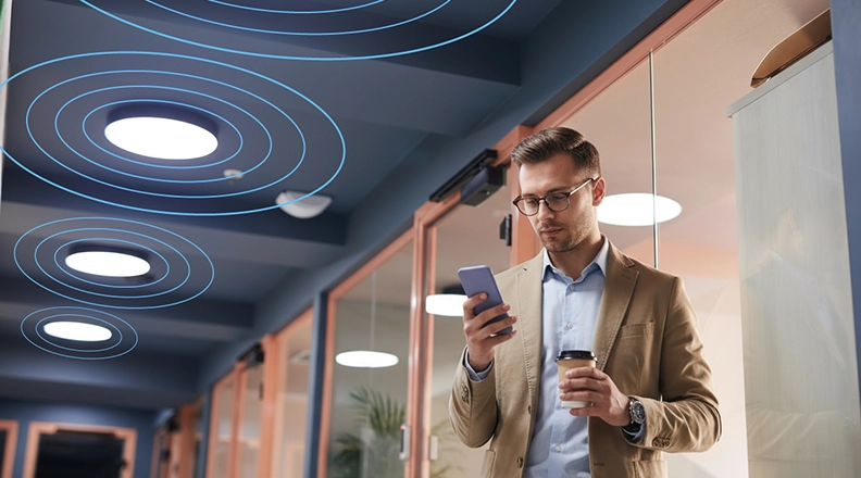


A 24 GHz Doppler sensor detects motion and measures how fast a target moves toward or away from it. It works in the dark, through plastic housings, and with antennas small enough to hide in a light fixture. CEL supplies two low noise GaAs FETs for the RF front end: the CE3520K3 for the LNA, PA driver or oscillator, and the CE3514M4 as an oscillator option.
This post covers how the sensor works, where it beats PIR and where it does not, and what the CEL datasheets specify.
How a Doppler Sensor Works
The sensor transmits a continuous wave, typically in the 24.00 to 24.25 GHz ISM band. A moving target shifts the frequency of the echo by 2 × speed × carrier frequency / speed of light.
At 24.125 GHz that works out to about 161 Hz per m/s of radial speed. A person walking at 1 m/s produces a tone near 160 Hz. The mixer output sits in the audio range, so a low-cost MCU ADC can sample it.
Three limits of a plain CW Doppler design:
- Direction (approaching or receding) needs an I/Q mixer with two outputs in quadrature. A single-output mixer gives speed only.
- Range is not measured. Distance needs FMCW or FSK modulation.
- Only radial motion counts. A target moving across the beam at constant distance produces little or no shift.
24 GHz vs 5.8 GHz vs PIR
| 24 GHz Doppler | 5.8 GHz Doppler | PIR | |
|---|---|---|---|
| Wavelength | 12.4 mm | 51.7 mm | Not applicable (thermal IR) |
| Doppler shift per 1 m/s | About 161 Hz | About 39 Hz | Not applicable |
| Antenna size | About 4x smaller in each dimension than 5.8 GHz | Larger patch | Needs an IR-transparent lens |
| Speed output | Yes | Yes | No |
| Through plastic housing | Yes | Yes | No, needs a lens window |
| Ambient light and temperature | Not affected | Not affected | Can false-trigger on heat sources and drafts |
| Coverage through walls | Lower, more attenuation | Higher | None |
The last row cuts both ways. Higher attenuation at 24 GHz keeps a sensor from triggering on motion in the next room, a problem 5.8 GHz sensors are prone to. It also means less coverage past obstacles.
Radar has its own false triggers. Ceiling fans, HVAC vents and vibrating fixtures all move. Plan on filtering in firmware: speed thresholds, dwell time, or a signal-strength floor. A person sitting still can also drop out of detection unless the design is sensitive enough to pick up breathing-level motion.
Glass is not transparent to 24 GHz in every case. Plain glass passes some signal with loss. Metal-coated or low-E glass can block it. Test with the real cover material.
Front-End Signal Chain
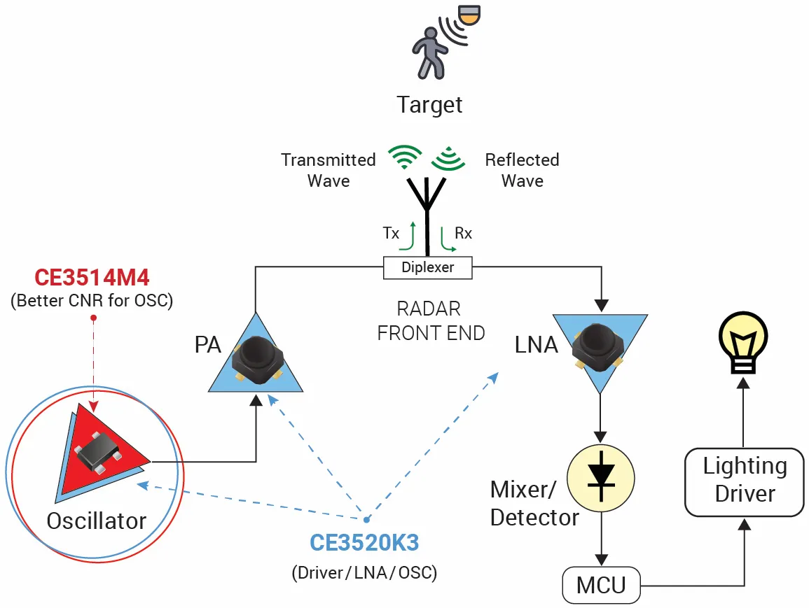
- The oscillator generates the 24 GHz carrier.
- The PA drives it through a diplexer to the antenna.
- The echo returns through the diplexer to the LNA.
- The mixer or detector combines the echo with the carrier and outputs the Doppler tone.
- The MCU filters the tone and decides whether to act.
- The MCU switches the lighting driver, door motor or alarm.
The LNA noise figure sets how weak an echo the sensor can hear, which sets detection range for a given transmit power. The oscillator’s carrier-to-noise ratio (CNR) matters because oscillator noise mixes down into the same low-frequency band as the Doppler tone.
CEL Parts for the Front End
| Part | Role in CEL reference design | Datasheet performance | Package |
|---|---|---|---|
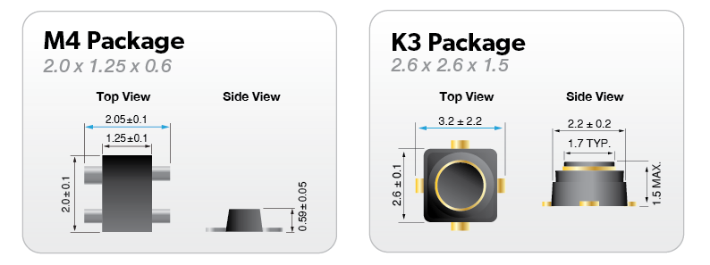
| CE3520K3 | LNA, PA driver or oscillator | NF 0.55 dB typ (0.80 max), Ga 13.8 dB at 20 GHz. NF 0.80 dB typ, Ga 13.9 dB at 24 GHz | K3 Micro-X hollow plastic, 2.6 x 2.6 x 1.5 mm |
| CE3514M4 | Oscillator, for better CNR | NF 0.42 dB typ, Ga 12.2 dB at 12 GHz | M4 flat-lead 4-pin super minimold, 2.0 x 1.25 x 0.6 mm |
Both are rated at VDS = 2 V, ID = 10 mA. The recommended range is 1 to 3 V and 5 to 15 mA, with 125 mW total dissipation and an operating range of -55 to +125 °C (derated per the datasheet curve). The CE3520K3 datasheet lists Doppler sensors as a target application.
Know what the datasheets do and do not cover:
- The CE3520K3’s 24 GHz figures are typical values, not tested on production parts. Its 20 GHz figures are 100% tested.
- The CE3514M4 datasheet specifies performance at 12 GHz only. Its oscillator phase noise and output power at 24 GHz depend on your resonator and layout. Measure them on your board.
Using the CE3520K3 in all three positions keeps the BOM to one part number. Using the CE3514M4 as the oscillator is the option CEL’s reference diagram shows for better CNR, and it takes less board area.
Typical Applications
- Automatic doors and gates. Detect approach and ignore people walking past, using direction from an I/Q mixer.
- Smart lighting. Hide the sensor inside the fixture behind a plastic lens or diffuser.
- Security. Detect motion in the dark and through a plastic enclosure.
- HVAC and building control. Feed occupancy to setback logic.
- Industrial monitoring. Detect motion around machinery where dust or heat defeat optical sensors.
- Vital signs. Chest motion from breathing can be detected at short range. This takes careful signal processing, and it is not a medical measurement without clinical validation.
Design Resources
- Low Noise Devices: datasheets, S-parameters and distributor links
- K2, K3, M4 Layout Guide (PDF)
- CE3520K3 S-Parameters
- CE3514M4 S-Parameters
- K2 and K3 Recommended Soldering Flux and Cleaning Conditions (PDF)
Need samples or help with a 24 GHz front end? Use the form below and a CEL engineer will follow up.